DifCal
A Program for Calculating Diffracting Angles with a Diffractometer.
Available as both an iPhone and iPad app, the screen shots below are for the iPhone version.
The iPad version has all views on a single screen.


Difcal is based on the original paper by Busing and Levy (Acta Cryst 22, 457, 1967). Follow-on work by Brennan (Rev. Sci. Instrum. 63, 992 1992). Z-axis geometry work based on Brennan, et al. (Nucl. Instrum. & Meth. A291, 86, 1990).
Diffractometer Calculations
Although most programs which control diffractometers (e.g. at a beam line) have built-in capabilities for
calculating where to expect a given reflection from a given crystal to occur, it can be helpful to have an idea where to look
before arriving at the synchrotron. Difcal is a handy iPhone or iPad-based application which allows the user to explore where to
find various reflections, how changing the incident photon energy will change those positions, and how they will change based on
which constraint is used for a particular diffractometer. Perhaps most usefully if there is a question of how to mount the crystal on the
diffractometer in order to access a specific set of reflections playing with the Orient View (and thus the orientation matrix) will be very helpful.
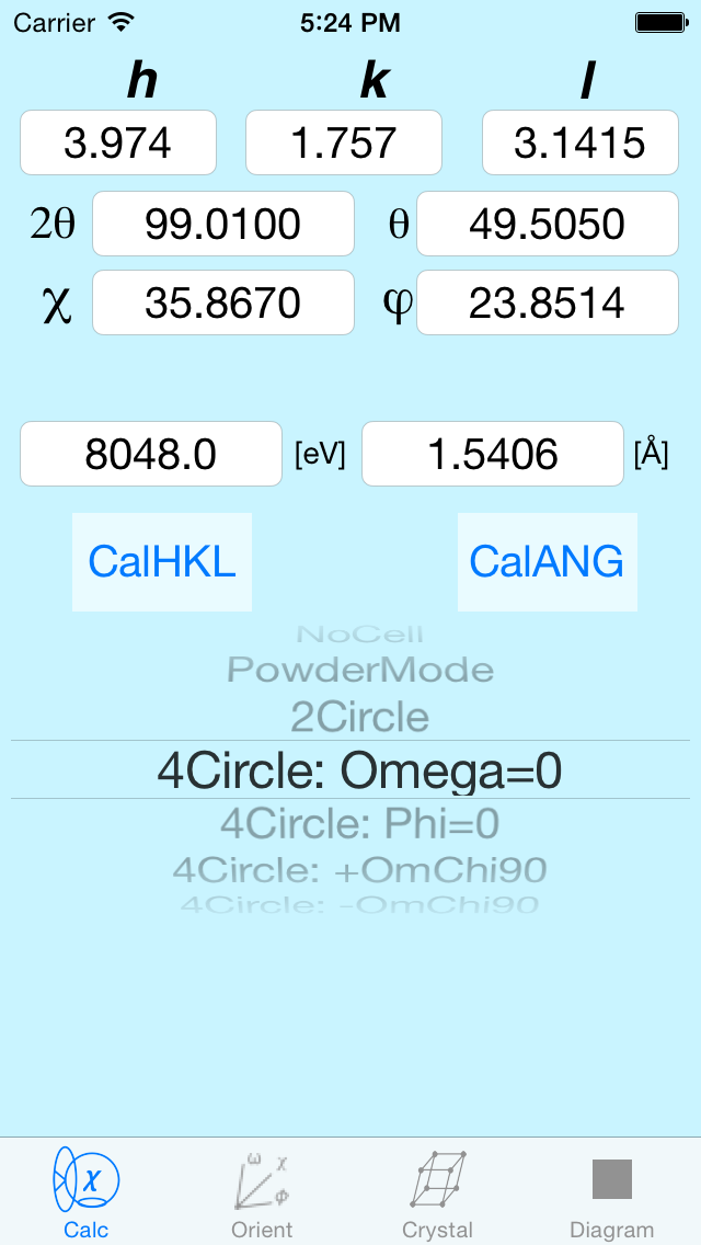
In addition to the standard 4-Circle, Z-Axis and Theta-Theta diffractometers calculations are also shown for simpler geometries such as 2-Circle, Powder Mode and, for amorphous materials, a "No Cell" mode where the results are reported in inverse Angstroms rather than in reciprocal lattice units.
4-Circle Diffractometer and its various options
The original 4-Circle diffractometers at the Oak Ridge reactor where actually three-motor diffractometers:
the same clock motor drove both the detector (2Theta) and Theta angles simultaneously, but in a 2-1 ratio. This is not a
particular drawback because a true 4-Circle diffractometer has one too many degrees of freedom. You can get to any reflection
with a surprisingly large set of Theta, Chi and Phi positions. By locking Theta to half of 2Theta you remove the extra degree
of freedom and you have a unique solution for any reflection. There are times when you might want a different restriction. The choices given here
are to set Phi=0 or to set Chi = 90 with either a positive or negative Omega. Omega is the difference between Theta and half of 2Theta.
Z-Axis Diffractometer and its options
For a number of in-situ growth chambers there are advantages of keeping the sample surface
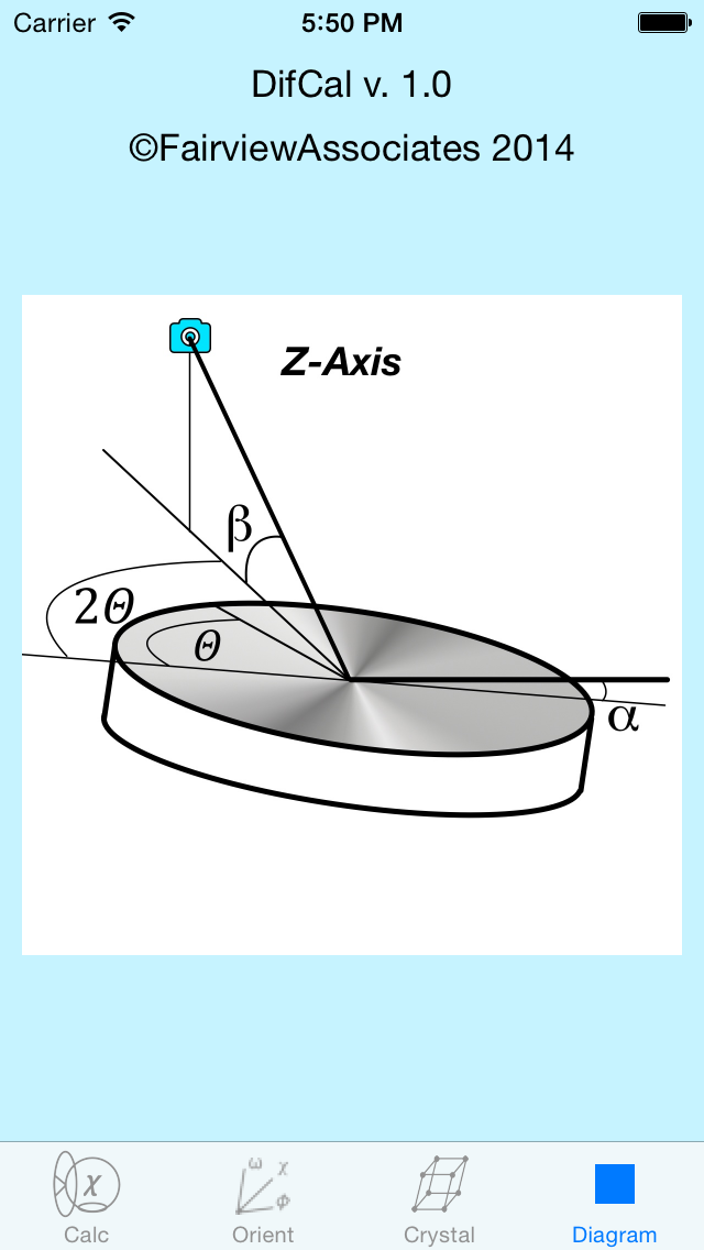
normal nearly fixed and rotate the scattering plane rather than keeping the scattering plane in the vertical. The first of these growth chambers was built by Brennan and Eisenberger (Nucl. Instrum. & Meth. 222, 164 1984). In this case the Chi and Phi circles are replaced by Alpha (the grazing angle of incidence on the sample) and Beta (the take-off angle from the sample). There are four options for calculations using the Z-Axis mode. The first (and most common) is Alpha fixed. In this case the grazing angle on the sample is set (typically to something small) and the other three angles respond for each reflection. Not all reflections are accessible in this geometry (which is true of all four of the Z-Axis modes). The advantage here is that for the case of a large sample chamber not moving it too often has real advantages. The alternative is if you don't have the ability to change the take-off angle of the detector, in which
you fix Beta. If everything is light and fast-moving Alpha=Beta gives you access to the largest number of reflections.
Theta-Theta Diffractometer
This instrument is more commonly used with a lab-based X-ray source, as both the source and detector rotate about the sample rather than having everything rotate about the incident beam.
2-Circle Diffractometer
Primarily used for powder diffractometery, a 2-circle instrument can be used to look at a set of reflections that are in a plane (i.e. (h,k,0) reflections.
Powder Diffractometry
For powder diffractometry the 2Theta value is calculated for the magnitude of the reciprocal lattice vector, i.e. sqrt(h^2+k^2+l^2). Thus only 2Theta is reported.
Amorphous (No Cell) Diffractometry
For the case of an amorphous material where there is no unit cell the 2Theta value is based on the size of the scattering vector in inverse Angstroms ( q = 4*pi*sin(Theta)/lambda ). A handy rule of thumb: because 4*pi is roughly equal to the conversion from wavelength to energy, q_max is roughly equal to the incident energy in keV. So if you need to get to q of 10, you'll need at least 10 keV x-rays.
Orientation Matrix View
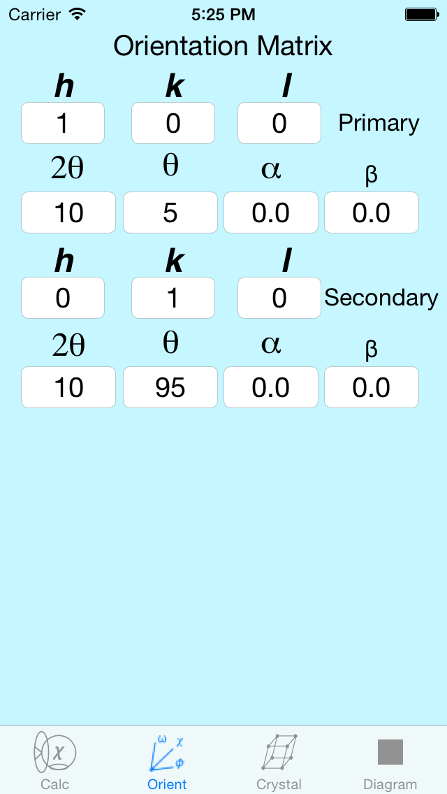
One of the most difficult aspects of learning to drive a diffractometer program is understanding the Orientation Matrix. In order for the code to know where to go to find, say, a (1,1,1) reflection, you have to tell the program how you've mounted the crystal on the diffractometer. Merely telling it you have a silicon single crystal isn't sufficient, you also have to say that (e.g.) the 001 reflection is along the phi axis and the 100 reflection is perpendicular to it. On the Orient view this translates into the primary reflection being a 001, and Omega, Chi, Phi are 0, 90, 0. The secondary reflection is 100 and for that reflection Omega, Chi, Phi are 0,90,0. Life gets more complicated for monoclinic and triclinic crystals. Also, there is a special Orientation Matrix for the Z-axis diffractometer. For the math to work you have to give real (but arbitrary) values for 2Theta.
Crystal Definition View
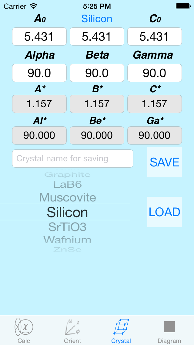
The program comes pre-loaded with a number of different crystal structures but more can be added
by the user. Simply enter in the new a0, b0, c0, alpha, beta and gamma values for your crystal, give a crystal name and hit the Save button. The greyed out text boxes are the reciprocal space values corresponding to the real space values you've entered.
Diagram View
As one changes the calculation mode on the first page, the schematic on the Diagram View will
change. Each schematic shows the important angles and their relationships.
Comments, Suggestions?
difcal@fairviewassociates.com


